Revolutionary mechanical parts with additional shapes play a crucial role in various industrial sectors, from automotive to aerospace. These complex parts, incorporating a variety of geometries, require advanced mastery of manufacturing and design processes. This article explores the techniques and challenges associated with the production of these components, highlighting recent innovations and best practices to ensure their optimum quality and performance.
Definitions
A mechanical part is essentially represented geometrically by flat and cylindrical surfaces (helicoidal, conical, spherical, etc.) whatever their relative positions and orientations:
- A plane is defined geometrically by a position, an orientation and no intrinsic dimensions.
- A cylinder is defined by the position and orientation of its axis, and an intrinsic dimension, its diameter.
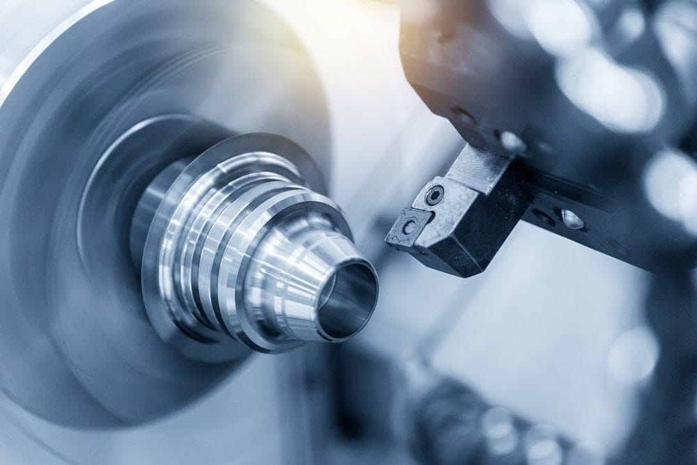
A part of revolution is essentially composed of coaxial cylinders, cones and spheres, with faces perpendicular to the part's axis of revolution.
A revolution part with additional shapesis composed of cylinders, cones, coaxial with perpendicular faces and holes, faces, grooves with offset axes.
Which methodology for which part?
Mechanical parts known as revolution parts (60%) are becoming increasingly complex, as the number of surfaces and features to be produced increases. To machine these different part morphologies, we use lathe-type machine tools with enough digitized axes to generate all the surfaces to be produced in a single fixture (geometric positioning of a part in its working environment). These machines feature 2 digital axes, X and Z.
All these turning machines are available in single-spindle and twin-spindle versions, and in single-turret, twin-turret and tri-turret versions for twin-spindles. By increasing the number of turrets or spindles, you can machine several surfaces in parallel.
Indeed, the aim of companies is to increase their productivity and to have a high level of autonomy on a workstation, so as to free the operator to carry out other tasks in hidden time, such as preparing the launch of a new part, production control, preparing a new NC program, etc.... To achieve this, the machine must offer an ever-increasing potential of tools, and therefore of machining operations, so that the maximum number of operations can be carried out without requiring operator intervention. Production time, optimized from the point of view of cutting conditions, produces a maximum number of surfaces in a single set-up. The use of a single fixture has a further advantage in that it enables greater geometrical precision to be achieved, since the difference in tool displacement relative to the workpiece depends solely on the machine's capability.
What are the difficulties involved in machining mechanical parts?
The problem of quality control in the production of parts stems essentially from two factors:
- Dispersed positioning of workpieces on the workpiece holder by human intervention (poor repeatability) during the second or nth machining phase.
- Controlling the position of the tool cutting surface in relation to the workpiece. Correction of the positions and orientations of the various physical tools is managed by one or more tool correctors, which can be used to modify the tool trajectory.
- Part measurement, which if not perfectly controlled, will lead to variability in machine set-up.
Solutions
To solve these problems, it is undoubtedly necessary to address the problem of isostatic positioning of the part, so that human intervention in positioning is kept to a minimum.
Once the problem of positioning has been resolved, we need to obtain a measurement value for the part that is as accurate, faithful and repeatable as possible. To achieve this, human intervention (a source of considerable variability) must be kept to a minimum. Coordinate measuring machines such as the Zeiss Duramax provides a very interesting solution, because it's both comprehensive and effective.
The numerical control drives the tools according to the geometric coordinates in the programming reference frame (part), but also according to the position and orientation parameters of the machine, workpiece holder and tool holders. If the part's characteristics are not correct, the parameters linked to the various tools (gauges, or dynamic correctors, offsets, etc.) must be corrected for a specific position.
Conclusion
Machine control is becoming more and more complex for set-up engineers, especially if you want to be able to control all characteristics while keeping them under control (SPC). Automated Process Control offers the possibility of doing this while optimizing corrections without risk. The combination of a coordinate measuring machine and Automated Process Control software improves the production of complex parts.
